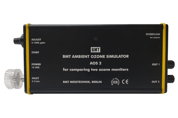
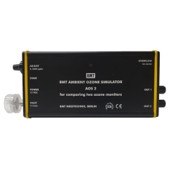
The AMBIENT OZONE SIMULATOR AOS 2 is a simple and universal means for comparing two ambient ozone monitors (UV photometric) with each other, or comparing an ozone sensor (electro-chemical) with an ozone monitor as a reference.
The small box contains an ozone producing UV lamp, its highThe small box contains an ozone producing UV lamp, its highvoltage power supply, and an air pump delivering more thanthree liters per minute of thoroughly filtered room air. Ambientozone monitors usually are breathing one liter per minute orless. Thus the simulator AOS 2 delivers more ozonated air thannecessary for two ozone monitors.
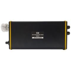
Power is supplied by a small wall-mount power adaptor. ThisPower is supplied by a small wall-mount power adaptor. Thiswide range power supply comes with three different exchangeableconnectors for use in Europe, UK, USA, and Japan.
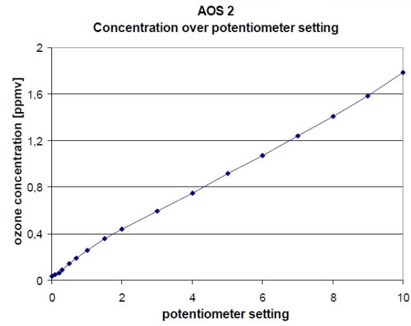
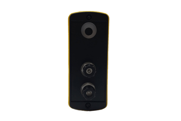
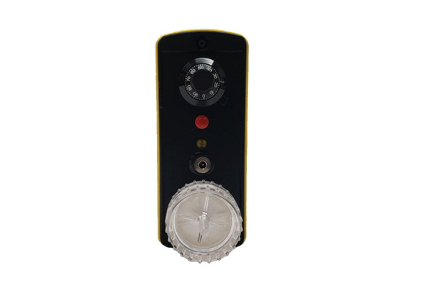
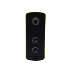
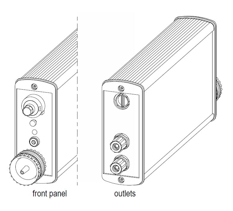
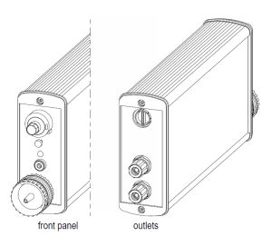
With a 10-turn potentiometer the ozone content of the air leavingWith a 10-turn potentiometer the ozone content of the air leavingthe AOS 2 can be set from about 40 to 1000 ppbv. Thisozonated air is leaving the instrument via a manifold with twoseparate outlet fittings: one outlet for the device under test, andthe other outlet for the reference ozone monitor. The overflow ofozonated air is leaving the manifold via an ozone destruct.
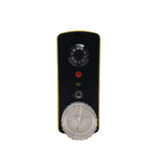
In the instrument's front panel a small window is providedIn the instrument's front panel a small window is providedthrough which the UV lamp can be watched. This window has aradiation filter to remove any dangerous radiation.
Click For Detail View
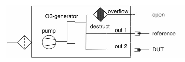
Alternatively, the overflow outlet can be closed. Now the AOS 2Alternatively, the overflow outlet can be closed. Now the AOS 2becomes an ozone blower: the reference monitor is connectedwith one outlet whilst the other outlet is blowing out about twoliters per minute of ozonated air, the ozone content of which ismeasured and indicated by the reference ozone monitor:
- comparison of two ambient ozone monitors
- comparison of electro-chemical sensors with a reference monitor
- ozone source generating 40 - 1000 ppbv in air at 3 l/min
- built-in pump
- setting with 10-turn potentiometer
- UV lamp monitoring window
- two independent ozone ports
- ozone destruct for overflow
- ozone blower function
- particle filter at inlet p;ort
- small, light weight, portable
feed gas ambient air through particle filter
particle filter replaceable insert, glass fiber felt
inlet flow rate 3 l/min (inlet)
sum of outlet flow rates must be smaller than inlet flow rate
max. ozone concentration > 1 ppmv
power setting with 10-turn potentiometer
adjustment range approx. 40 ppbv to more than 1000 ppbv
life expectancy of UV lamp > 5 years at continuous operation
temperature 10 to 40o C
gas outlet port for 4x6 mm or 5/32" x 1/4" FEP (PTFE)
power 12 VDC, 450mA wall mount adapter 100-240 VAC included
dimensions (WxHxD) 220 x 108 x 42 mm
weight 900 g
Typical relation between potentiometer setting and output: